How to Draw Column Grid in Autocad
Making the Best-Ever Sheet Layout Grid
The best way I know of to organize a drawing sheet in AutoCAD is by using a well-designed sheet layout grid . This is also the best way to organize an entire set of drawings.
A sheet layout grid is a hidden grid of cells that are used to place views, view titles and other elements within the work area of a sheet.
This simple tool helps to ensure that your entire set of project documents looks unified, orderly and professional.
In this post, I'll share some of my thoughts and recommendations on creating a sheet layout grid for use in AutoCAD projects. These observations are based on years of experience working with large, medium, and small-sized design firms. Some of these firms had great systems in place, some were just getting started, and some were holding on to old organizing systems that did not work well at all.
A later follow-up post will discuss the actual use of our layout grid in a typical project. In this post, we will create our layout grid.
Why Use a Sheet Layout Grid?
We all want our project documents to look clean, neat and professional. Often, someone reading the documents can — and will — form his or her judgment of the quality of a set of drawings within a few seconds, just by glancing through a few of the sheets and noting their overall appearance and consistency.
Whether it's fair to judge a set of drawings this way or not, this tendency by people to make quick judgments means that we designers, drafters, and CAD managers must strive to ensure that our drawings are organized carefully before they go out into the world.
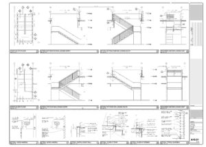
Example of a detail sheet with a hidden layout grid for the views

Horseshoes land wherever they land. Views, I think, should be placed logically.
For me, one quick tip-off that the drawings are not carefully organized is seeing a sheet containing several views that have "landed" like thrown horseshoes in more or less random locations around the available space on the sheet. This gives the impression that the work was done quickly, haphazardly and without much thought. It's also a sign that the designer was working without an organizing system for the sheets. An example would be a sheet containing, say, ten or twelve detail views, with each view just floating randomly around on the page.
On the other hand, a well-organized sheet has views arranged in an orderly system, usually some type of grid. The grid lines may be visible or hidden. The important thing is that a system that makes visual sense has been adopted, and followed consistently.
Avoiding the "Jumpy" Drawing Syndrome
Another "tell" of a lack of care in the creation of a set of documents is when I see views of a similar type and scale appearing on different sheets, but not positioned consistently from one sheet to the next. An example would be a series of floor plans of various types (demolition plan, construction plan, ceiling plan, and so on). These similar views need to be positioned precisely and consistently on the sheet.
The popular use of multi-page PDF files for sharing a set of drawings makes it especially obvious when sheets are not consistently laid out. A client can easily flip through multiple sheets by tapping a "PgDn" or "PgUp" key on their computer. As the viewer flips through the pages, any misalignment between similar views on successive sheets causes a "jumpy" effect that is very noticeable and can be distracting.
Set a high standard! Sooner or later, someone will notice.
Knowing this, I suggest that you create a multi-page PDF of your set and use it to check your set of drawings for uniformity. If your repeating plans (or sheet numbers, title blocks, or anything else) appear to "jump around" as you flip through the sheets using Page-Up and Page-Down, you know what you need to fix before sending the set out to your client/supervisor/co-workers. Set a high standard! Sooner or later, others will notice.
A Crucial Tool: The Sheet Layout Grid
The designer's number-one tool to better organize your views, sheets, and the entire set of project documents is the sheet layout grid. In this post, we will create a sheet layout grid step-by-step, in order to clarify the decisions we make along the way to achieving the final product.
To design the layout grid, we need to know the exact size of the work area — the area inside the border, not including the title block.

Title block with border
For our example, let's visualize a 36″ wide by 24″ high sheet, typically referred to as a 24×36 sheet. For this discussion, let's say that the design firm's title block, containing the design firm name, project name, professional seal and so on, are in a vertical strip about 2 3/4" wide running along the right edge of the sheet. Additionally, there are border lines all around the sheet. These are useful to separate the unprintable margin areas from the usable area of the sheet. These lines are about 5/8″ in from the top and bottom edges, and 3/4″ in from the right edge (where the title block sits). The border line on the left side of the sheet is 1 1/2″ in from the sheet's edge, to allow space for staples and binding.
The Sheet Notes Area (Optional)
Also, I've learned that it's very useful to set aside a vertical band of space, just to the left of the title block, for such things as sheet notes, legends, keynotes, and so on. This vertical band is 3 3/4″ wide in this example. This is optional, but I recommend that you give it a try. I learned this trick while working at a highly successful international architecture and interiors firm, and now I would not want to give it up.
This leaves an open "work area" or "white space" about 27 1/4″ wide by 22 3/4″ high, in which we will place our views.
Sizing the Cells
Next, we will subdivide the remaining work area into a grid of cells. We do this in order to have a consistent framework on which to "hang" our views. We also need to allow space for the view titles with their scale notations, which typically live below each view.
How big should each cell be? That depends upon the size of your typical detail views. For this discussion, let's say that a typical detail view is about 6″ square. Adding some extra space below the view for the view title and scale notation, I'm going to set the "target" size of my typical layout cell to be approximately 6″ wide x 7″ tall.
I'm thinking in this post about stair details or cabinetry details. Depending on the nature of your work, the size of your typical details may be different. Still, I think a detail about the size of a 5″ x 8″ index card is easy to work with and feels natural.
Designing the layout grid
Using the DIVIDE Command
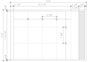
Experimenting with AutoCAD's DIVIDE command, we find that we can fit a grid of 12 cells on our 24" x 36" sheet, four cells wide by three high, each cell measuring 6 7/8″ wide x 7 5/8″ high. See image at right.
If your typical details are a different size, just adjust as needed. It's the concept that I'm offering here. I want to subdivide the large, empty work area into a grid of equally-sized cells that will easily accommodate my typical views in a grid-type arrangement.
If some larger details require two or more cells, that's fine. We just need a framework that we can stick to a good portion of the time, a system that works "in most cases." Also, if claiming multiple cells for a view results in a bit of white space around the view, that's OK. I'll live with that, for the benefit of having a great-looking sheet.
Here is an additional factor to consider. In order to make sure that my layout grid always aligns perfectly with my title block/border, I'm going to draw the outline of the border as part of my layout grid block. I will also draw the outline of the 24″ x 36″ sheet and clearly mark the origin point (0,0 coordinates) to make it easy to place in perfect alignment with my title block/border.
Obviously, you'll want to pin down the dimensions of your title block/border before you coordinate the size of the layout grid with the title block/border.
Drawing and Saving the Final Layout Grid
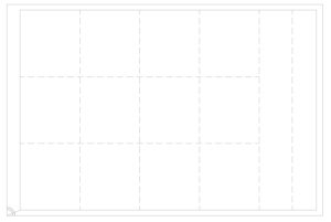
The final 24″ x 36″ layout grid
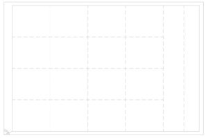
This 24″ x 36″ grid is for interior elevations
With these decisions made, here (at left) is a screenshot of my new layout grid. I made it entirely of defpoint-layer lines. I'll place a "master" copy of the layout grid block inside of a DWG file, saved in the company's library. I can copy and paste the block from the library file into each project working file using the Windows clipboard. This beats using xrefs, in my view. Xrefs can get their paths broken too easily. This way, the grid lives inside the working file.
In my particular business (architecture and interior design), there are some views which tend to be very wide and not very tall, namely interior elevations. For these views, I will make a variation on the standard layout grid. This variation will be four cells wide by four (instead of three) cells tall. I'll give this block a different name, adding the letters IE for Interior Elevations. See the image at right.
Adjusting the Grid to a Larger Sheet
Most firms have multiple sheet sizes for different sizes of projects. It's always good to save paper when we can. However, this requires us to make a layout grid for each sheet size.
The two 24" x 36" sheet layout grids we made previously will have to change when we go to a different sheet size, say 42" wide by 30" high. Unfortunately, there is no perfect way to make the same cell size work in both sheet sizes.

Layout grid for a 42″ x 30″ sheet
My solution is that I'm going to subdivide the 30" x 42" sheet into 42 cells, seven wide x six high, each cell being 6 5/8" wide X 7 1/4" high. See the image below. These are close to the size of the cells of my 24" x 30" sheet. For the interior elevations layout grid, I'll make the grid five cells tall, rather than four.
To finish up, I'll create "master" office-standard DWG files, each file containing one of the layout grid blocks I've made, and save the files in the firm's central CAD library. For example, my file list now reads:
• LAYOUT GRID 24×36.dwg (for general use)
• LAYOUT GRID IE 24×36.dwg (for interior elevations)
• LAYOUT GRID 30×42.dwg (for general use)
• LAYOUT GRID IE 30×42.dwg (for interior elevations)
Summing it up
One last thing. Personally, I believe a sheet of drawings looks much better if you hide and just imply the organizing grid. I know that some firms like to show the grid on the printed page. To me, that makes the sheet look a bit heavy-handed.
To strengthen the grid, I like to use a view title block that snaps to the grid intersections and looks like a horizontal band below the actual view. The view title block can stretch as needed to snap to the grid intersections. See the stair detail example near the top of this post. This makes the implied grid more "solid" and flexible, without the rigidity of visible grid lines.
I hope this study has been helpful and maybe expanded your view of the best way to make a useful sheet layout grid. We're now ready to insert the layout grid into our project. In a follow-up post, I will show how to use the layout grid we just created in a typical project. You may be surprised at some of the powerful results we get from the decisions we made in this study.
Your thoughts? Suggestions? Please leave a comment below.
Until then, have a great day, and . . .
Keep on CADDing! 🙂
Mark
(Visited 1 times, 1 visits today)
Source: https://bestcadtips.com/power-of-sheet-layout-grid-autocad/
0 Response to "How to Draw Column Grid in Autocad"
Post a Comment